Effective Flexible Printed Circuit Board
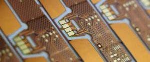
A flex printed circuit board (abbreviated FPC) is a flexible circuit that has conductive traces on a thin, flexible substrate that is often a polyimide film. A flex PCB is used to connect electronic components, replacing traditional wires in many applications. It allows for more design freedom than a standard PCB and offers advantages over hand-wired or soldered connections, such as resistance to mechanical stress and electromagnetic interference.
The flexible printed circuit board can be manufactured by a variety of techniques, depending on the specific needs of a project. The fabrication process usually includes the use of photo imaging or laser imaging to create the pattern for the conductive copper traces on a dielectric layer, typically polyimide. A flex circuit may also be made from other materials such as polyamide or epoxy-and-glass fiber. The conductors are then bonded to the dielectric with an adhesive such as epoxy, hot-melt or solventless bonding.
In order to provide a stable base for the conductors, a flex PCB should have a substrate material that is resistant to heat and moisture. Polyimide is the most common choice, offering excellent thermal properties and durability. It is also tolerant to repeated solder reflow cycles, and can expand or contract with temperature changes. It is also very tough, able to withstand high loads and shocks.
What Documentation is Necessary for Effective Flexible Printed Circuit Board?
It is important to select the appropriate copper conductor size for a flex circuit, particularly when the board will be subjected to frequent bending or movement. In general, a smaller diameter conductor will be more resilient than a larger one. In addition, a thinner foil can be more flexible than a thicker one. If the flex circuit will be subjected to dynamic stress, it is recommended that the conductors be coated with a protective material such as gold or solder.
Another important consideration for a flex circuit is the thickness of the adhesive layer that holds it together. While this is not as critical as the substrate or conductor thickness, it is crucial that it be selected properly. Too thick an adhesive could lead to delamination, which is the breakdown of one or more layers of the flex circuit. Too thin an adhesive could cause the conductors to be exposed and prone to corrosion and shorting.
In the realm of modern electronics, where miniaturization, efficiency, and flexibility are paramount, Flexible Printed Circuit Boards (PCBs) stand as the unsung heroes. These remarkable electronic interconnects have revolutionized the way electronic devices are designed, manufactured, and utilized. With their bendable, lightweight, and adaptable nature, flexible PCBs have become the backbone of countless electronic applications, from smartphones and wearable devices to medical implants and aerospace systems.
To avoid these problems, the design engineer must ensure that the dimensions and thicknesses of all insulating and non-conductive layers are accurately documented in the design. The design should also clearly show the layer arrangement and materials used in the flex circuit, as well as the thickness of the substrate.