components arranged on an rigid flex pcb fabrication
Rigid flex PCBs are widely used in electronic devices due to their ability to accommodate complex layouts and harsh operating conditions. Understanding how these boards are assembled is essential for achieving high-quality, efficient circuit designs capable of meeting stringent performance criteria. To achieve this, engineers and fab houses must implement best practices for assembling rigid-flex circuits including optimizing the stackup configuration, ensuring adherence to assembly standards and guidelines, and incorporating pre-assembly baking. Baking prior to assembly mitigates moisture-induced degradation, preventing solder joint cracking and component damage.
Components mounted on a rigid flex pcb fabrication are connected with vias that are either copper or metal plated. The use of copper vias reduces the potential for stress concentration spots, which may otherwise result in structural failures. To minimize stress, designers should ensure that the diameter of a via is larger than the connecting traces’ breadth. Adding teardrop (pad fillets) or annular rings to vias can also help avoid stress concentration spots and improve the strength of the connection.
When designing a rigid flex pcb, engineers must consider how the board will bend, flex, and fold during operation. This will affect the physical dimensions of the board, the location of lands and pins, and the placement of components. To prevent the board from delaminating, it’s important to use rigid substrate materials with a minimum thickness of 20 mils. It’s also a good idea to incorporate a buffer layer between the flexible layers and the rigid core.
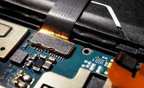
How are components arranged on an rigid flex pcb fabrication?
Another key consideration when designing a rigid flex is to properly plan the layer arrangement. This will help to maintain the integrity of the flex section while maximizing signal integrity and thermal management. It’s also important to use proper impedance matching techniques when routing signals. Finally, thermal vias should be carefully placed to enable efficient heat dissipation in different sections of the board.
As a whole, flex and rigid-flex circuits are a popular choice for manufacturing wearable technology, medical equipment, and automotive systems. This is because flex PCBs can be folded or bent to conform to the shape of the device, while rigid-flex circuits allow for the integration of electronics into non-planar spaces like inkjet printers and automotive dashboards.
Moreover, the ability of rigid-flex circuits to withstand mechanical stresses makes them suitable for consumer electronics such as mobile phones and tablets. They are also popular for wearable tech such as fitness trackers and smartwatches. Lastly, rigid-flex PCBs are ideal for industrial automation solutions, as they can withstand harsh environments and rugged operating conditions. In addition, they can be designed to fit in confined spaces for space-saving design. This makes them an excellent option for electronics manufacturers seeking to reduce their overall production costs by integrating rigid and flexible components into a single product.